The robot is powered using two BLDC outrunners with roughly 200 W and 1000 rpm/V, going through planetary transmission and toothed belt to the wheels (See the mechanincs page for photos). The total transmission ratio is approximately 137:1, maximal speed is 1.5 m/s.
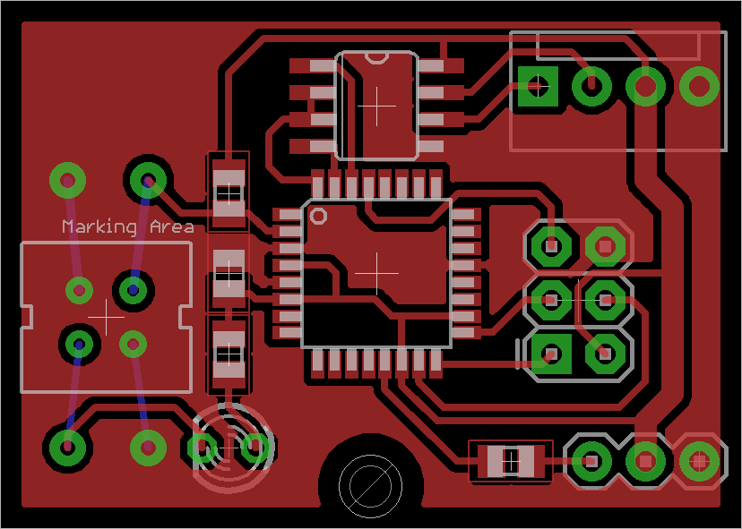
Each motor is connected to 25A TrackStar car ESC, which is in turn controlled by a custom driver board mounted directly over the motor. The board is designed to be as simple as possible, single layered and with as little soldering as possible (but the TQFP package of the atmega proved to be too much for me anyway :-) ).
Basically the board has only a CNY70 reflective sensor that reads eight black stripes on the silver motor can, ATMega8, RS485 transceiver and a few connectors.
The sensor is connected with a resistor as a voltage divider and fed to the Timer/Counter0 clock source pin of the mega, relying on its input filtering / whatever a MCU digital input pin does. I’ve had some problems with not counting all ticks at some distances from the motor, but after a going through a few resistor values it seems to work reliably enough.
Drive board software counts the encoder ticks and generates PWM signal to control the ESC using PID controller.
The motor board communicates with the bus master over RS485 and layer2 thingie. The interface handles initialization, debugging and the main update request. Each update contains a desired speed in ticks per 10ms, reply reports the actual measured number of ticks since the last update.
Most of the encoder tick counting is done by the Timer/Counter0 which is clocked by the sensor output pin.
There are two separate places where the number of ticks must be processed –
when replying to the command on RS485 and when updating PID, so the counter is kept
running at all the times and allowed to overflow instead of reseting after each event.
When value of the counter is needed, it is atomically read using the functions
latch_encoder_ticks8 or latch_encoder_ticks16.
These functions atomically calculate a difference from a previous remembered state
and update the state to current counter value.
To assure that the functions are atomic, we rely on the fact that the motor doesn’t
spin too fast and that at most one encoder tick may happen while it is running,
meaning that if we detect a tick during reading, it is enough to simply read everything
again.
Because at top speed we might clock more than 256 ticks per one 100ms update interval, the counter
is extended to 16 bit in software (simple ++ticksHigh in the overflow interrupt handler).
On the other end the we had a problem that hardware counter on atmega can only count
rising or falling edges, but not both.
That would limit the resolution to 8 ticks per motor revolution
even though there are eight recognizable edges on the motor can.
To avoid this limitation the binary value of the input pin with the sensor value
is treated as another counter, which causes the Timer/Counter0 to count on overflow.
At the end we effectively have three counters, chained together: 1 bit pin state,
8 bit Timer/Counter0 and 8 bit variable ticksHigh.
These are all stuffed into a single 16 bit final counter value (dropping the most significant
bit).
The PWM signal for controlling the ESC is generated using 16 bit Timer1, through the servo mini library. In the current version PWM is running at 100 Hz (as opposed to 50 Hz standard for analog servos).
The value fed to the ESC is calculated using a PID controller. The PID update code piggybacks on Timer1 overflow interrupt, which was unused by the PWM generating code.
The controller code is fairly straightforward, calculates error as a difference of number of ticks ordered in the previous command to the number of ticks since last PID update. This means that the servo update frequency determines units used for requested speed commands.
To prevent integrator windup, its value is clamped (to the output range of the servo library, but this was a pretty arbitrary choice).
To avoid some of the noise in the differential term, the differences are smoothed over a few last ticks (4 in current version).
Controller parameters can be set at runtime over RS485 (this has helped a lot during debugging). All PID calculations are done in fixed point format with 2 fractional bits.
Update frequency, smoothing interval and parameters multiplier are stored in the interface file and compiled in.
Because there is only a single sensor measuring ticks, there is no way to directly measure the rotation direction. This however is not much of a problem, because the transmission ratio is so high, that forces on the wheels don’t move the motor (I didn’t try too hard, though, I was afraid the force could strip the teeth on the belts). The only problem that remains is to change directions of the motor reliably. To do this the drive board software has a small state machine that waits until there were at least four PID update cycles with zero ticks measured until the motor can start moving again.
BLDC motors are cool, but using sensorless ones is PITA. The starting performance is terrible (maybe better ESC would help?), they jump, stutter and whine until they get over about 1000 rpm (that is 10 mm/s), then they start working perfectly again. I will use sensored motors for my next robot.
